A few weeks before I flew out to copenhagen, I had caught up with a friend doing research in computer vision (not HCI/fabrication). After describing my research interests in materials-driven fabrication and sustainability, he was quiet for a second and then asked me, “Isn’t manufacturing fully automated now by robots and such? Why do we need the humans in those kinds of workflows?” I had no experience with robotic manufacturing to be able to respond confidently – until I started at #cita.
At CITA, I was put on one of the existing projects, ReShelter. One of the tasks assigned to me was to support one of the other researchers (pseudonym, JH) in the robotic fabrication of a forest shelter using reclaimed wood beams from multiple sources such as an earlier CITA research project (RawLam).
On the first day, I was introduced to their fabrication lab with the giant (and intimidating) ABB-branded robotic arm with a spindle at the end for milling. JH had shown me the Rhino file with the entire shelter design, and everything seemed perfect and ready to go. He showed me the Grasshopper workflow to generate the CAM files and transporting them to the robot controller. Then, we would “jog” (or manually move) the robot end effector to a position close to the starting position of the CAM toolpath and let the controller adjust to the exact position.
Outside of the fabrication lab is a giant pile of reclaimed wood, covered in tarp and wood scraps to keep the tarp from flying away. This was the wood that we would be using for the project. The tarp did not seem particularly protective of the wood. In fact, when we first removed the tarp to retrieve certain beams, rainwater hidden in the folds of the tarp gushed out, partially onto the wood beams. JH was not concerned – reclaimed wood will constantly change anyway. This attitude was one that I was not familiar with – materials will change and we will adapt. Coming from using 3D printers or laser cutters, where materials were standardized and CAD/CAM were defined, I was uneasy with the comfort that the researchers had with materials that constantly change. What shocked me more is how JH told me that we do not have any extra pieces – every timber beam was specifically designated for a part of the final structure without any extras.
Of course, the piles of timber themselves were also challenging to sort through as well. Every timber had markings with a number (sometimes on both ends, sometimes only on one) and JH and I would spend time taking pieces off the pile to retrieve a few beams and then put them back to avoid leaving them exposed and spreading the materials on the courtyard of the campus. When I asked JH how he chooses the order of which materials to mill, he loosely described how beams with similar cut patterns are easier to do together and once you get into a groove, it is easy to rinse and repeat with the same setup, fixturing, and sequence of operations.
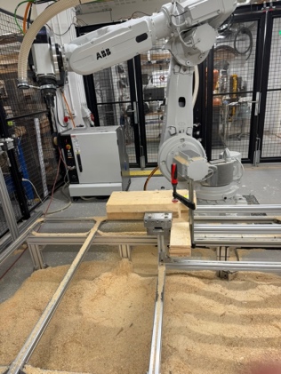
JH had taught me the basics of using the robotic mill. After a few mornings of working with JH, we got into a groove; JH would set up the CAM files, and I would operate the controller for milling. The process would begin with fixturing – the timber could not move despite the immense force being applied onto the timber. For the shorter pieces that could not fit into both the clamps, we had to improvise as shown on the left.
Most of the other pieces (at least so far) followed some variation of the following steps (apologies for the crude drawings):
-
Sawing to Size
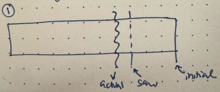
The reclaimed lumber beams were not made to size. The way that the beams were prepared was by taking two pieces of reclaimed timber and gluing them together. However, the pieces were (more or less) cut to similar size. They were labeled prior to my arrival of which beams were associated with which parts of the final structure (therefore, if a beam needed to be longer that was already predetermined). There were still pieces that were too long or even pieces that contain two of the final beams. The robot mill would take too long with that much excess wood – so we had to go manual and just use the saw to cut (-ish) to size. We would leave a bit extra for the robot to make precise cuts but if we didn’t do this, the robot fabrication would take forever (wasting time).
-
Profile Check
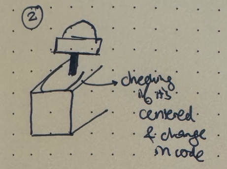
Profile check was a check without any action on the timber beam. The grasshopper code had an offset slider, and we measured to see how centered the profile cut would be as per the timber beam, we had. We would use the calipers and move the spindle slowly along the toolpath. If it was off slightly (under 1-2mm), we would ignore it. But the centering was more off, JH would adjust the code to offset (“better to change code, not physical setup”).
-
End Cut
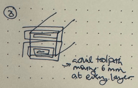
Then, we would begin the actual milling process. The robot would go in a spiral pattern and JH would program it to be in the air for a few rounds and we would change the speed based on what initially felt like “vibes.” After a few rounds of milling where I would be cautious and run fabrication at 50% speed, I realized that the slower speed would have a higher likelihood of causing the timber to shake in the jig. Faster speeds would be louder but often result in cleaner cuts. Any splinters that resulted from the cuts would be okay – JH shared that these artifacts (better term?) are normal and could be cleaned up later.
-
Pocket
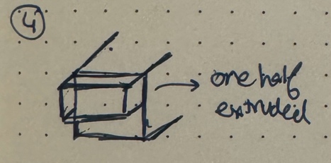
For a reason that I’m still unsure about, the end cut would be split up into another step called “profile” that made the difference between the top/half of the beam more substantially different as per the CAD model. We wouldn’t need to move the robot between steps 3 and 4.
-
Profile
Next was the actual profile cut. I would have to jog the robot to a location that is close to the starting point of the toolpath. If I didn’t do this, the robot would try to take an “optimal” path to the starting point that could hit the piece of wood itself or the actual frame. Also, there was an interesting issue that JH was worried about. There was a plastic connector for a wire and the spindle itself that cracked. That meant that if there was too much pressure applied (or if the wire was pulled too hard/fast), the wire would be yanked out. That meant that any movement of the robot arm had to be done extremely carefully and we would have to go to the robot and pull the wire to reduce how taut the wire was. Although there is a maintenance person for the robot, they are not on site (in Stockholm) and therefore, it’s faster and more convenient for the researchers to try and resolve the issues themselves.
-
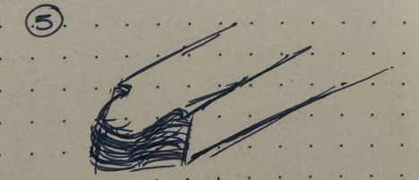
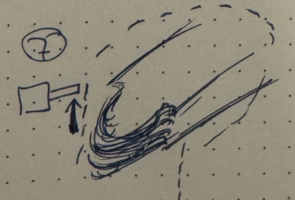
Wings
The wings were a “dangerous” toolpath due to the wire issue. But the milling itself was super-fast; it would be just an arch movement, but the first time we did it, the wire got yanked and we had to spend some time fixing it. So usually, we run this path at 25-50% speed.
-
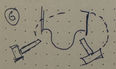
Trace
The final milling step was mostly for assurance that if the joints were not cut perfectly, they could still be slotted together during the final assembly. This cut was just two lines. It was interesting that even upon fabrication completion, the assembly feels daunting with all the things need to be adjusted. The actual fabrication itself is such a small part of the process (and there are inevitable mistakes) – the precision happens in the planning and then adapting the pieces to “work” happens during assembly. On the wall of the fabrication lab is a spreadsheet printout with every beam to be fabricated along with notes specifying reminders that could be addressed during assembly.
While robots have immense capabilities to increase the precision of fabrication, they also have high risk. What if the fixturing isn’t done well and the wood shakes? What if the robot arm turns in a weird way and hits the piece (potentially damaging the robot)? What if a robot part breaks (and you’re pressed for time)? While the robot seems indestructible, I realized how fragile it really is. Every piece of wood took about 2-3 hours, contingent on everything going smoothly. I’m curious to observe more about this tension and negotiation between computational tools ( computing ) and the human (not operator, but collaborator) and how they both come to reach a “steady state” of fabrication.